I bought a Yamaha Pacifica PAC120H a while back. I wanted a guitar that I could use as a testbed for hardware experiments. Ideally, an inexpensive guitar, so that I wouldn't care too much about ruining it. I've played a lot of guitars over the years, so I was pretty shocked when this almost-bottom-of-the-range instrument turned out to be one the best sounding and best feeling guitars I'd ever played.
It did, however, have a slight grounding issue (the guitar would quietly hum until you touched any metal component). It was also fairly noisy when the coil split was engaged. This isn't exactly unexpected; when the coil split is engaged, one of the coils is disabled and therefore the hum cancelling property of the humbucker is also disabled.
I'd heard of people applying shielding to the interiors of guitars in order to reduce noise, so I decided to try it. Shielding essentially involves covering every surface of the guitar's internal cavities with conductive material. There are lots of options here, but the cheapest and simplest appears to be common garden copper tape (with conductive adhesive).
I bought a couple of rolls of this:
I tested it with a multimeter and it had roughly the expected resistance for copper of that thickness. I also checked that the adhesive was actually conductive, and it did appear to be.
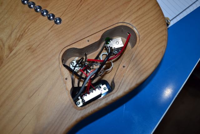
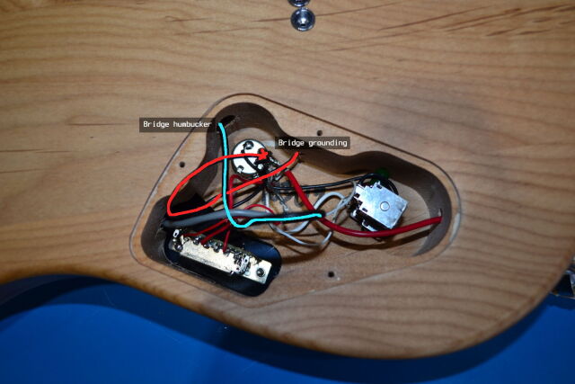
I opened the guitar, and was presented with bad wiring. The Pacifica series has a slightly frustrating design where it's simultaneously front-routed and rear-routed. Most guitars pick one or the other, so that when you're doing work on the internals, you don't have to work on both sides of the guitar simultaneously. The wiring was chaotic, and wired in an order that meant desoldering many components just to move one wire:
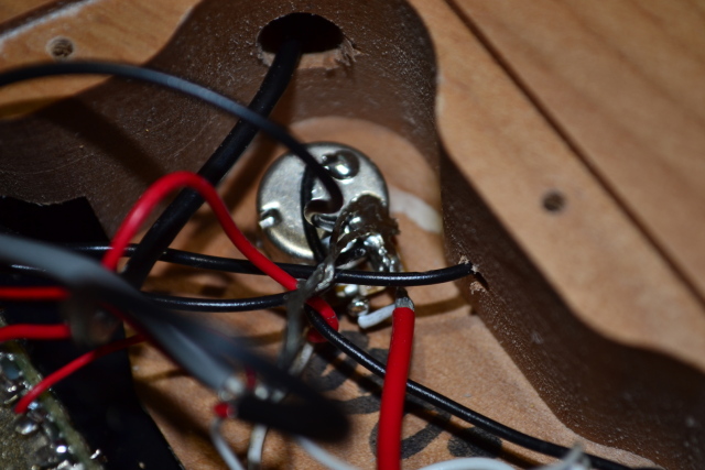
The wiring also followed the horrific guitar convention of soldering every ground cable to the volume pot, resulting in a giant compost heap of solder:
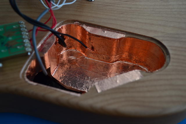
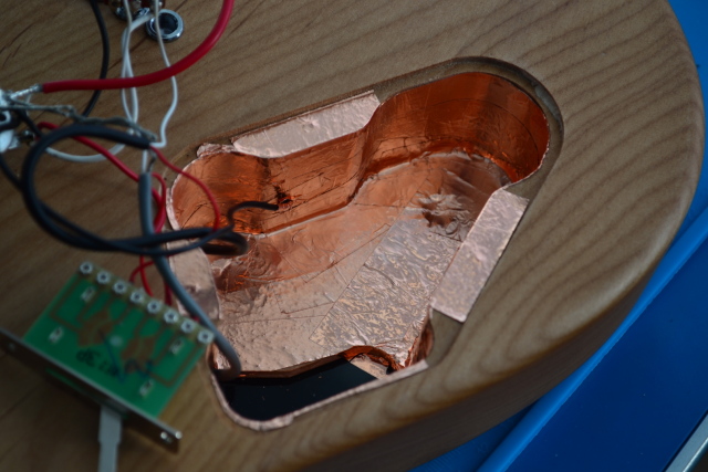
I ended up ripping out all the components in the process of applying shielding to the cavity:
Unfortunately, the ground pin of the volume pot had been mutilated in the process of soldering the pin to the casing along with everything else. Clearly someone just grabbed the pin with a pair of needle-nose pliers and bent it around as hard as they could until it made contact with the casing. Rather than try to fix that mess, I replaced the volume pot with something with the same specifications.
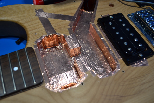
I took off the scratchplate and shielded it and all the front cavities too, leaving plenty of excess so that the back of the scratchplate would be in contact with the internal shielding in as many places as possible.
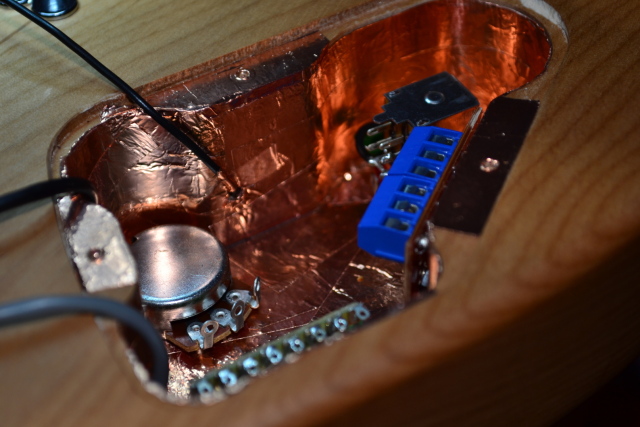
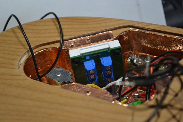
With a fresh volume pot in place, I didn't want to repeat the convention of soldering everything to it. I fabricated a little block with some screw-in terminals on it that could be mounted inside the back cavity that essentially provided a solderless connection to ground for all of the things that needed to be connected to ground.
Unfortunately, I constructed the board such that the screw terminals ended up mounted too high in the cavity. This meant that, with (or without) cables plugged into it, there would be no way to get the backplate on without squashing the cables somewhat.
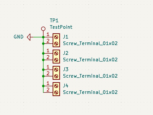
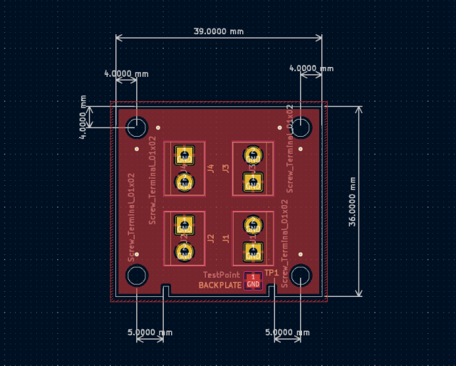
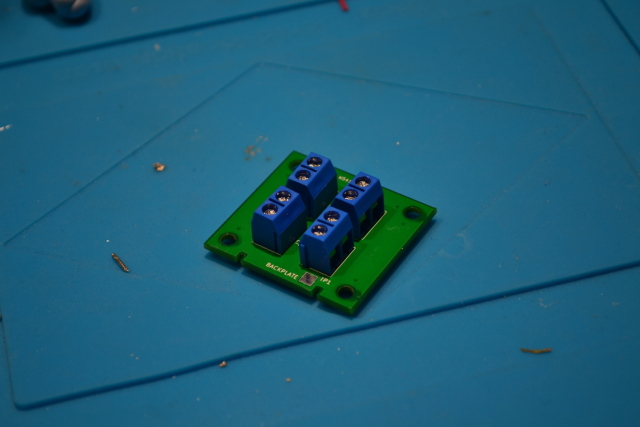
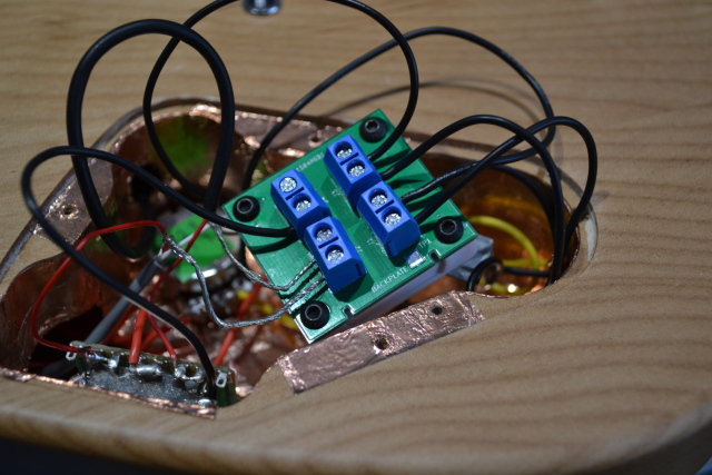
Continuing the theme of overengineering, I decided the best and most compact way to get a good quality ground connection would be to have a small PCB made with eight side-mounted screw terminals on it. The small cavity makes it extremely difficult to get any kind of screwdriver into the cavity in order to loosen or tighten screws, so I decided that the most pleasant way to work would be to have something that could be attached and detached without tools that could host the connections. It would then no longer be necessary to try to jam a screwdriver into the cavity to work on anything.
I put together the most idiotic circuit ever designed in KiCad:
I uploaded the resulting Gerber files to pcbway and had some nice printed PCBs a week later. After soldering on the screw terminals the result was obviously far better than the original perfboard construction:
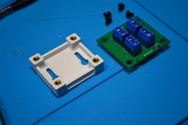
I didn't want to fix the PCB directly to the guitar. I instead designed and printed a small mounting plate that could be hooked onto a pair of wood screws inside the cavity.
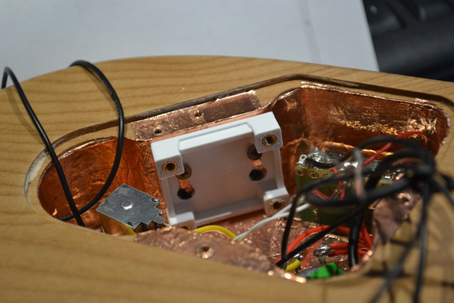
Mounting the plate and PCB inside the cavity was painless, and the resulting solderless connections are solid. I subjected them to more-than-the-minimum amount of violence, and was unable to get the wires to come out of the connectors when screwed in.
With the backplate back on, I strung the guitar with the cheapest, worst strings I could find (as I fully expected to have to take the strings off again to fix one or more accidental grounding problems). I plugged the guitar in and ... it worked!
So was it all worth it?
Well, I took a recording of the guitar before I added the shielding. Compared
with a recording taken with the new shielding and wiring in place... Noise
levels are lower by 1dB. At least the wiring is now actually maintainable.
Join us again next week when we disassemble a washing machine to reduce the length of the rinse cycle by 3.2 seconds.
