After a lot more back and forth with Bosch support, I finally got an actual answer.
The serial number on a Dremel is written on what they refer to as the "data plate" on the side of the tool. The number doesn't match what's in any of the QR codes on the tool, and it isn't labelled as being a serial number.
It's a 3-4 digit number, followed by a date of the form MM/YYYY.
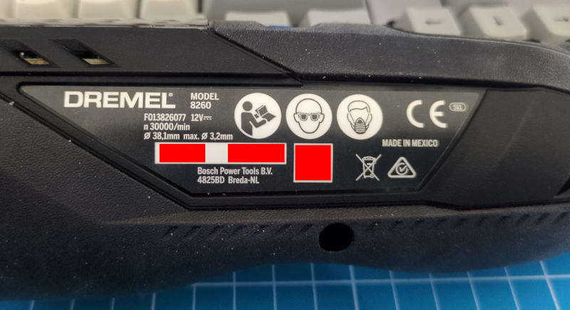
If the first number was 179 and the date was 02/2024, then the serial
number of the tool would be, apparently, 0179022024.
I'm in the process of migrating io7m.com to Hetzner.
My previous setup on Vultr consisted of a single bastion host through which it was necessary to tunnel with ssh in order to log in to any of the multitude of servers sitting behind it.
This has downsides. Anything that wants to access private services on the hidden servers to perform monitoring, backups, etc, has to know about all the magic required to tunnel through the bastion host. When I first set up those servers, Wireguard didn't exist. However, clearly Wireguard now exists, and so I've incorporated it into the new arrangement on Hetzner instead of having to painfully tunnel SSH all over the place.
The goal is to essentially have the servers that sit behind the bastion host
appear as if they were ordinary hosts on my office LAN, whilst also not being
accessible from the world outside my LAN. This is achievable with Wireguard,
but, unfortunately, it requires a slightly complicated setup along with some
easy-to-forget bits of NAT and forwarding. In my case, at least one of the NAT
rules is only necessary because of what I assume is an undocumented
security feature of Hetzner private networks, and we'll get to that later.
There's also a bit of MTU unpleasantness
that isn't required if you aren't using PPPoE to access the internet.
I'm documenting the entire arrangement here so that I have at least a fighting chance of remembering how it works in six months time.
This is the basic arrangement:

On the left, workstation01 and backup01 are two machines in my office LAN
that want to be able to reach the otherwise unroutable server01 and server02
machines hosted on the Hetzner cloud. The router01 machine is, unsurprisingly,
the router for my office LAN, and router02 is the Hetzner-hosted bastion
host. All IP addresses here are fictional, but 70.0.0.1 is supposed to
represent the real publically-routable IPv4 address of router02, and the other
addresses indicated in blue are the private IPv4 addresses of the other
machines. My office LAN is assumed to cover 10.20.0.0/16, and the Hetzner
private network covers 10.10.0.0/16.
This is also intended to be a strictly one-way arrangement. Machines on my
office LAN should be able to connect to server01, server02, etc, but no
machine in the Hetzner private network will ever have any reason to connect
in to my office LAN.
Wireguard (router02)
The first step is to set up Wireguard in a "server" style configuration on
router02. The configuration file for Wireguard on router02 looks something
like this:
[Interface]
Address    = 10.10.0.3/32, 70.0.0.1
ListenPort = 51820
MTU        = 1410
PrivateKey = ...

[Peer]
# Router01
AllowedIPs   = 10.10.100.1/32
PreSharedKey = ...
PublicKey    = ...
This configuration specifies that Wireguard listens on UDP port 51820 on
10.10.0.3 and 70.0.0.1 for incoming peers. The first strange thing in
this configuration is that we only define one peer and specify that its allowed
IP address is 10.10.100.1. Packets with a source address of anything else will
be discarded. This address doesn't match the address of anything on the office
LAN, so why are we doing this? This brings us to...
Wireguard & NAT (router01)
We specify a single peer on router02 for reasons of routing and configuration
sanity; we want to treat all connections coming from any of
workstation01, backup01, or router01 as if they were coming straight
from router01, and we want router01 to appear as just another ordinary
host on the 10.10.0.0/16 Hetzner private network. Unsurprisingly,
we achieve this by performing NAT on router01. router01 is running BSD
with pf, and so a pf rule like this suffices:
nat on $nic_wg1 from $nic_dmz:network to any -> ($nic_wg1)
That should be pretty straightforward to read: Any packet with a source
address matching the network of the NIC connected to the office LAN
(10.20.0.0/16) will have its source address translated to the IP address of
the Wireguard interface (10.10.100.1). The address 10.10.100.1 is
deliberately chosen to be one that we know won't conflict with anything we have
defined in the Hetzner private network.
We then use a Wireguard configuration on router01 that looks like this:
[Interface]
PrivateKey = ...

[Peer]
AllowedIPs          = 10.10.0.0/16
Endpoint            = router02.io7m.com:51820
PreSharedKey        = ...
PublicKey           = ...
PersistentKeepalive = 1
We specify a client configuration that will attempt to connect to
router02.io7m.com. We specify that the allowed IPs are 10.10.0.0/16.
In this context, the AllowedIPs directive indicates that any packets
that are placed onto the Wireguard interface that don't have a destination
address in this range will simply be discarded. Because router01 is a
router, and therefore will forward packets it receives, if either of
workstation01 or backup01 attempt to connect to, say, server01, their
packets will ultimately be sent down the Wireguard network interface prior
to having their source addresses translated to 10.10.100.1 by the pf
NAT rule we configured above.
At this point, any of the machines on the office LAN can try to send packets
to server01, server02, etc, but those packets won't actually get there.
The reason for this is that router02 isn't currently configured to actually
route anything, and so those packets will be dropped.
Routing On router02
The first necessary bit of configuration is to set a sysctl
on router02 to enable IPv4 forwarding:
# sysctl net.ipv4.ip_forward=1
At this point, any of the machines on the office LAN can try to send packets
to server01, server02, etc, but those packets still won't actually get
there. This is an entirely Hetzner-specific problem and/or feature depending
on your point of view, and it took quite a bit of debugging to work out what
was happening. It wouldn't happen on a physical LAN, to my knowledge.
Hetzner IP Security(?)
It seems that there's some kind of anti-spoofing system at work in Hetzner private networks that the above setup will trip. Consider what happens here:
workstation01sends a packetAtoserver01.- Packet
Ahas source address10.20.0.1and destination10.10.0.1. - Packet
Areachesrouter01and undergoes NAT. The source address is transformed to10.10.100.1. - Packet
Agoes through the Wireguard tunnel and emerges onrouter02. router02sees the destination is10.10.0.1and so dutifully forwards the packet toserver01.server01mysteriously never sees packetA.
What I believe is happening is that an anti-spoofing system running somewhere
behind Hetzner's cloud network is (correctly) noting that packet A's source
address of 10.10.100.1 doesn't correspond to anything on the network.
There are no servers defined in Hetzner cloud that have
that address as it's a fiction we've created with NAT to make our Wireguard
configuration less complex. The anti-spoofing system is then silently dropping
the packet as it's obviously malicious.
To correct this, we simply apply a second NAT on router02 such that we
transform packets to appear to be coming directly from router02. The following
nft ruleset suffices:
table ip filter {
	chain FORWARD {
		type filter hook forward priority filter; policy accept;
		iifname "wg0" oifname "eth1" accept
		iifname "eth1" oifname "wg0" accept
	}
}
table ip nat {
	chain POSTROUTING {
		type nat hook postrouting priority srcnat; policy accept;
		ip saddr 10.10.100.1 oifname "eth1" snat to 10.10.0.3
	}
}
We set up forwarding between the wg0 (Wireguard) and eth1 (Hetzner private
network) NICs, and we specify a NAT rule so packets with a source address
of 10.10.100.1 are transformed such that they get a source address of
10.10.0.3.
After enabling these rules, workstation01 can send packets to server01
and get responses as expected. From server01's perspective, it is receiving
packets that originated at router02.
It's slightly amusing that we introduce a fictional address on router01 to
simplify the configuration, and then undo that fiction on router02 in order
to satisfy whatever security system Hetzner is using. This is what running out
of IPv4 address space gets us.
Years ago, I had to deal with some
aggravation around IPv6. My connection to my ISP is such that I'm
using PPPoE which means I have to use an MTU of 1492 instead
of the ubiquitous 1500 that everyone else is using:
# ifconfig tun1
tun1: flags=1008051<UP,POINTOPOINT,RUNNING,MULTICAST,LOWER_UP> metric 0 mtu 1492
I'm using Wireguard in various places to link
multiple networks. Wireguard packets have 80 bytes of overhead, so the
virtual interfaces it creates have an MTU of 1420 by default.
You can probably guess where this is going.
On a connection such as mine, a packet of size 1420 plus the 80 bytes of
overhead is 1500. This means we'll run into all of the same problems that
occurred with IPv6 back in 2017, with all of the same symptoms.
The solution? Set an MTU of 1410 on the Wireguard interfaces.
On FreeBSD:
# ifconfig wg0 mtu 1410
On Linux, you can either use an MTU=1410 directive in the Wireguard
configuration file, or:
# ip link set mtu 1410 up dev wg0
Like any good obsessive, I keep an inventory of computer parts, tools, and so on. The inventory keeps track of serial numbers so that I can answer questions like "Which machine did that PSU end up being installed into?" and "When those addicts from that failing machine learning company broke in, which GPUs did they take?".

I recently bought a Dremel 8260 to do some guitar body routing tasks, and other miscellaneous bits of cutting and drilling. I've got no complaints with it, although I ran into a pretty immediate problem when trying to check it into the inventory.
Dremel are a division of Bosch, and it seems like Bosch have gotten into the habit of not putting serial numbers onto tools, or at least not doing it in any obvious way.
I have a Bosch GSB 18V-45 here and there's no serial number printed anywhere on the case. The same goes for the Dremel 8260.
There is, however, a QR code on both. Scanning the QR code on the drill yields the following redacted text:
240516_80103601JK3300_xxxxxxxxxxxxx
                      ^^^^^^^^^^^^^
The underscore characters are actually the U+241D GROUP SEPARATOR character,
but that wouldn't be printable in most browsers so I've replaced it with an
underscore here. The xxxxxxxxxxxxx string I've redacted because I believe it
actually is a serial number. The 240516 string looks like a date, but it
doesn't match up with anything date related on the tool itself (the tool is
from 2023). It presumably has some internal meaning to Bosch. If you dump the
string 80103601JK3300 into any search engine, the first result that comes
up is service information for the drill, so that number is presumably a model
number.
The Dremel has two QR codes. One QR code simply restates the model number, but the other QR code hidden inside the battery compartment yields:
240511_8010F013826077_xxxxxxxxxxxxx
                      ^^^^^^^^^^^^^
Again, dumping 8010F013826077 into a search engine yields service information
for the Dremel 8260, so it is probably a model number. The 240511 string means
something to someone somewhere at Bosch. The xxxxxxxxxxxxx string might
be a serial number.
Neither of the xxxxxxxxxxxxx values are actually printed anywhere on the
tools, and there's no documentation whatsoever online that I could find about
how to locate serial numbers on Bosch tools. I'm not up for buying another
instance of either tool just so that I can compare the xxxxxxxxxxxxx values.
Searching for those values online yields nothing, which in itself is evidence
that they might just be unique-and-otherwise-meaningless serial numbers.
I emailed Bosch to ask them where I can find the serial numbers on my tools. I got a supremely confusing message back saying that Bosch's legal team might be inspecting the message (?), followed a few days later by a message from a support team suggesting that I register the tool online. The message seemed to indicate that they hadn't read my initial message at all, or at least hadn't understood it. I did register the tools online and, predictably, this didn't result in the serial numbers being magically revealed (there's no way it could have; I wasn't even required to submit any kind of proof of purchase or scan anything on the tools, so presumably registration is just a way to get a bit of data out of me for marketing purposes).
I'm not sure what's so difficult about putting an unambiguous serial number somewhere visible on the case. Computer parts manufacturers seem to manage to do it just fine. Who benefits from keeping things obscure like this?
I'm planning to move hosting from Vultr to Hetzner. I can't fault Vultr, I've been with them since 2017. The functionality Vultr provide, their transparent pricing, and their technical support have all been great. I've often filed support tickets and had them resolved within a couple of minutes of posting.
However, Hetzner have better pricing (they'll give me roughly four times the compute resources for the same price as Vultr), have technical support that's reportedly equal to Vultr, and are based in a jurisdiction with stronger data protection laws. Additionally, they build and operate their own datacenters as opposed to renting space in someone else's, which really appeals to me as someone who tries to run as much of his own infrastructure as possible.
I'll have to add a Hetzner DNS plugin to certusine in order to issue certificates on the new infrastructure. That seems easy enough as the API looks almost identical to the one Vultr provide. I suppose there aren't all that many ways to manage DNS records.